How to Build a 7-Segment Display Encoder with Logic Gates
Introduction
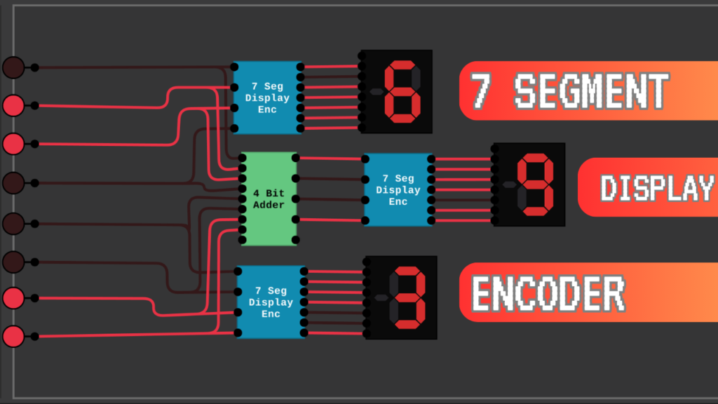
A 7-segment display is a fundamental component in digital electronics, commonly used to display numbers in calculators, clocks, and various embedded systems. But how do these displays know which segments to illuminate for each digit? This is where a 7-segment display encoder comes in.
In this guide, we will walk through building a 7-segment display encoder that takes a 4-bit binary input and converts it into segment control signals. Whether you’re a beginner looking to understand the basics of logic gates or an enthusiast seeking to optimize circuit design, this tutorial will provide a comprehensive breakdown.
Understanding the 7-Segment Display
A 7-segment display consists of seven LEDs labeled A to G, arranged to form numerical digits from 0 to 9. By selectively turning these segments on and off, we can represent different numbers. Here’s how the segments light up for a few numbers:
- 0: Segments A, B, C, D, E, and F are on (G is off).
- 1: Segments B and C are on.
- 2: Segments A, B, G, E, and D are on.
- 8: All segments are on.
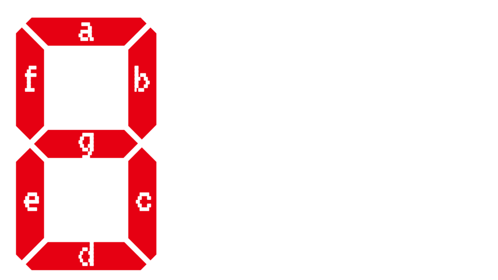
Each digit has a unique combination of segments that need to be turned on, which we will define using Boolean logic.
Defining the Logic for Each Segment
To control the display, we need to determine when each segment should be illuminated based on a 4-bit binary input (0000 to 1001 for digits 0-9). This can be achieved using Boolean expressions derived from a truth table.
Truth Table for Segment A (Example)
| Binary Input (DCBA) | A |
|---|---|
| 0000 (0) | 1 |
| 0001 (1) | 0 |
| 0010 (2) | 1 |
| 0011 (3) | 1 |
| 0100 (4) | 0 |
| 0101 (5) | 1 |
| 0110 (6) | 1 |
| 0111 (7) | 1 |
| 1000 (8) | 1 |
| 1001 (9) | 1 |
Deriving Boolean Expressions
Using Karnaugh Maps (K-Maps), we can simplify Boolean expressions for each segment. For example, the simplified equation for segment A might look like:
A=BˉD+AC+BDA = \bar{B}D + AC + BD
Similarly, we derive expressions for other segments B to G.
Building the Logic Circuit
Once we have Boolean expressions for all segments, we can create a circuit using basic logic gates:
- AND Gates – Used to combine input conditions.
- OR Gates – Used to sum multiple conditions.
- NOT Gates – Used for inverting inputs where necessary.
Step-by-Step Circuit Design
- Segment A Circuit:
- Use AND, OR, and NOT gates to implement the Boolean expression for A.
- Connect the appropriate 4-bit inputs to these gates.
- Repeat for Segments B-G:
- Implement simplified Boolean equations for each segment.
- Combine All Circuits:
- Connect all segment outputs to the corresponding LED segments on the display.
- Ensure all inputs come from the same 4-bit source.
Testing the Encoder
To verify the circuit, use:
- Binary Input Switches – Manually input binary values (0000 to 1001).
- Microcontroller (Optional) – Automate inputs for better testing.
- Simulation Software – Tools like Logisim or Proteus can visualize logic circuit operations before physical implementation.
Optimization Tips
To improve efficiency and reduce complexity:
- Use Multiplexers: Instead of using multiple gates, a multiplexer can streamline logic selection.
- ROM-Based Approach: Store segment values in a small ROM and read outputs based on binary input.
- Programmable Logic Devices (PLD): If working on FPGA or CPLD, use HDL (Verilog/VHDL) to implement logic more efficiently.
Conclusion
Building a 7-segment display encoder using logic gates is a great way to understand digital logic design. By breaking the problem into smaller sections—truth tables, Boolean simplification, and circuit implementation—you can efficiently design a robust encoder.
If you found this guide useful, consider sharing it with others, leaving a comment, or exploring related projects in digital electronics. Let me know if you have any questions!
FAQs
1. What is the purpose of a 7-segment display encoder? A 7-segment display encoder converts a 4-bit binary input into segment control signals to display numbers 0-9.
2. Can I use a microcontroller instead of logic gates? Yes! Microcontrollers like Arduino or PIC can directly control 7-segment displays using pre-programmed logic.
3. How can I simulate my design before building it? Use software like Logisim, Proteus, or Multisim to test the logic before assembling the circuit physically.