Meta Title: Build a 4-Bit Adder from Scratch – Simple Digital Logic Guide
Meta Description: Learn how to design and build a 4-bit adder using basic logic gates. This step-by-step guide simplifies digital logic concepts for beginners and enthusiasts.
Build a 4-Bit Adder from Scratch – Simple Digital Logic Guide
Introduction
Understanding digital logic is fundamental to designing and building electronic circuits. One of the essential components in digital electronics is the adder circuit, which is used in microprocessors and arithmetic operations. In this guide, we’ll explore how to build a 4-bit adder from scratch using basic logic gates like XOR, AND, and OR. We’ll start by constructing a 1-bit adder, then extend it to a 4-bit adder, and finally discuss how to scale it further. Whether you’re a student, hobbyist, or engineer, this guide will provide a hands-on approach to mastering digital logic.
Understanding Binary Addition
Before diving into the circuit, let’s review how binary addition works:
| A | B | Sum | Carry |
|---|---|---|---|
| 0 | 0 | 0 | 0 |
| 0 | 1 | 1 | 0 |
| 1 | 0 | 1 | 0 |
| 1 | 1 | 0 | 1 |
- The sum bit is computed using the XOR gate.
- The carry bit is generated using the AND gate.
- When adding two binary digits, if both are
1, the sum becomes0, and a carry is forwarded to the next bit.
Step 1: Building a 1-Bit Adder (Half Adder)
A 1-bit adder, also known as a half adder, performs binary addition on two input bits (A and B) and produces two outputs: Sum and Carry.
Logic Gates Used:
- XOR gate for the sum:
Sum = A ⊕ B - AND gate for the carry:
Carry = A · B
Half Adder Circuit:
 A ---|XOR|--- SUM
 B ---|   |
      |AND|--- CARRY
This basic circuit allows us to add two single-bit numbers, but it does not handle carry input from previous stages, which is necessary for multi-bit addition.
Step 2: Creating a Full Adder
A full adder expands on the half adder by incorporating an additional input: Carry-in (Cin).
Logic Equation for a Full Adder:
Sum = A ⊕ B ⊕ CinCarry-out = (A · B) + (Cin · (A ⊕ B))
Full Adder Circuit:
      A -------|
               | XOR |--- SUM
      B -------|     |
             | AND |   |
 Cin -------|     |   | OR |--- CARRY-OUT
             | AND |   |
      (A ⊕ B) ----|
This design ensures that we account for any previous carry, making it suitable for multi-bit operations.
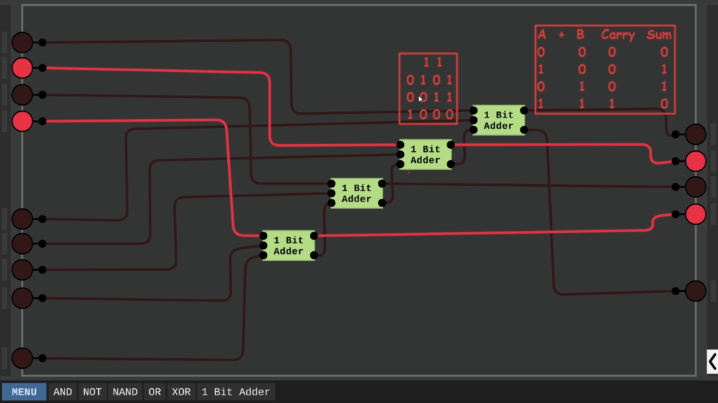
Step 3: Constructing a 4-Bit Adder
A 4-bit adder is built by chaining four full adders together. The carry output of one full adder is connected to the carry input of the next stage.
Each full adder in the chain takes two input bits and a carry-in bit, generating a sum and a carry-out bit.
Step 4: Extending to an 8-Bit or 16-Bit Adder
To build an 8-bit adder, simply connect two 4-bit adders together:
- The carry-out of the first 4-bit adder becomes the carry-in of the second 4-bit adder.
- This method can be used to scale the adder to 16-bit, 32-bit, or even larger bit-widths.
Multi-bit Adder Concept:
4-Bit Adder 1 ---> Carry-out ---> 4-Bit Adder 2
This modular approach allows for flexible digital circuit design.
Applications of a 4-Bit Adder
A 4-bit adder is a fundamental building block in:
- Arithmetic Logic Units (ALUs) in microprocessors.
- Digital counters and calculators.
- Binary multiplication and division circuits.
- Error detection and correction in communication systems.
Conclusion
Building a 4-bit adder from scratch is an excellent way to understand digital logic, binary addition, and combinational circuits. By mastering this concept, you can explore advanced topics such as multiplexers, flip-flops, and microprocessor design.
Are you interested in more digital logic projects? Subscribe to our newsletter, share your thoughts in the comments, and follow our channel for more tech tutorials!