Meta Title: Understanding Logic Gates: A Beginner’s Guide to Digital Circuits
Meta Description: Learn how basic logic gates like AND, OR, NOT, NAND, and XOR work with truth tables and simple circuits. A must-read for electronics and computer science enthusiasts!
Understanding Logic Gates: A Beginner’s Guide to Digital Circuits
Introduction
Logic gates are the fundamental building blocks of digital circuits. They are the core of computer processors, enabling complex computations using simple binary logic. Whether you’re an electronics hobbyist, a computer science student, or a tech enthusiast, understanding how logic gates work is essential for grasping the basics of digital electronics.
In this blog, we’ll break down the most common logic gates—NOT, AND, OR, NAND, and XOR—explaining their functions, truth tables, and how they form the basis of more complex circuits. Let’s dive in!
What Are Logic Gates?
Logic gates are electronic circuits that take one or more binary inputs and produce a single binary output. They operate using Boolean algebra and are represented using truth tables that define their behavior under different input conditions.
The basic logic gates include:
- NOT Gate (Inverter)
- AND Gate
- OR Gate
- NAND Gate (NOT AND)
- XOR Gate (Exclusive OR)
Each gate follows a unique logical rule that determines its output. Let’s explore them one by one.
1. NOT Gate (Inverter)
A NOT gate is the simplest logic gate, also called an inverter because it flips the input value.
- If the input is 0 (LOW), the output is 1 (HIGH).
- If the input is 1 (HIGH), the output is 0 (LOW).
Truth Table
| Input (A) | Output (NOT A) |
|---|---|
| 0 | 1 |
| 1 | 0 |

Example Use Case
- Used in circuits to invert signals, such as in memory and control units of processors.
2. AND Gate
An AND gate outputs 1 (HIGH) only when both inputs are 1. Otherwise, the output is 0 (LOW).
Truth Table
| Input A | Input B | Output (A AND B) |
|---|---|---|
| 0 | 0 | 0 |
| 0 | 1 | 0 |
| 1 | 0 | 0 |
| 1 | 1 | 1 |

Example Use Case
- Used in control circuits where multiple conditions must be met for an action to occur.
3. OR Gate
An OR gate outputs 1 (HIGH) if at least one of the inputs is 1.
Truth Table
| Input A | Input B | Output (A OR B) |
|---|---|---|
| 0 | 0 | 0 |
| 0 | 1 | 1 |
| 1 | 0 | 1 |
| 1 | 1 | 1 |
Example Use Case
- Used in alarm systems where multiple triggers can activate an alert.
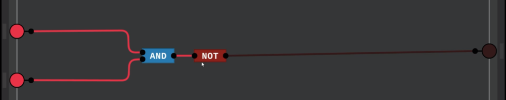
4. NAND Gate (NOT AND)
A NAND gate is simply an AND gate followed by a NOT gate. It outputs 0 only when both inputs are 1; otherwise, the output is 1.
Truth Table
| Input A | Input B | Output (A NAND B) |
|---|---|---|
| 0 | 0 | 1 |
| 0 | 1 | 1 |
| 1 | 0 | 1 |
| 1 | 1 | 0 |
Example Use Case
- Widely used in memory circuits and microprocessors.
5. XOR Gate (Exclusive OR)
An XOR gate outputs 1 only when the two inputs are different.
Truth Table
| Input A | Input B | Output (A XOR B) |
|---|---|---|
| 0 | 0 | 0 |
| 0 | 1 | 1 |
| 1 | 0 | 1 |
| 1 | 1 | 0 |
Example Use Case
- Used in arithmetic operations, such as binary addition.
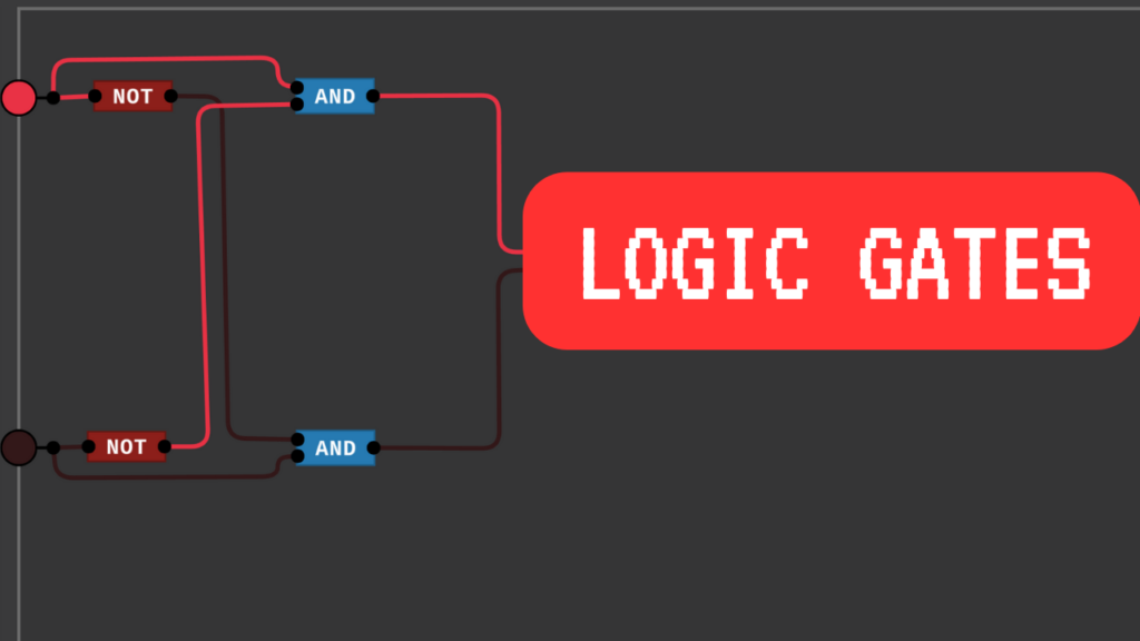
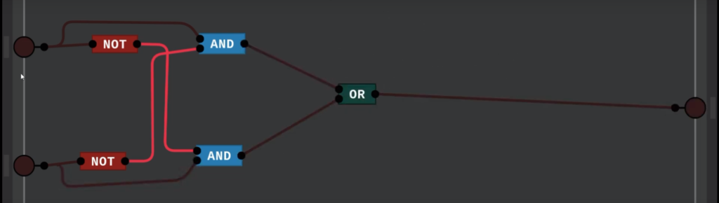
Combining Logic Gates
By combining these basic gates, we can create more complex digital circuits. For example:
- Half Adder: Uses XOR and AND gates to add two binary numbers.
- Full Adder: Extends the half adder by incorporating a carry-in bit.
- Multiplexers & Decoders: Built using combinations of AND, OR, and NOT gates.
Understanding these basic logic gates is the first step toward designing more advanced digital systems like microcontrollers, processors, and even artificial intelligence circuits.
Conclusion
Logic gates are the foundation of digital electronics, enabling everything from simple circuits to advanced computing devices. By mastering their functions and truth tables, you can begin exploring more complex digital systems.
What’s next? Stay tuned for our next article, where we’ll use these gates to perform more advanced operations. In the meantime, try experimenting with a logic gate simulator to solidify your understanding!
Call to Action
- Share this blog with friends who are interested in digital electronics!
- Comment below with any questions or insights.
- Subscribe to our newsletter for more tech tutorials!
Tags: logic gates, digital electronics, binary logic, AND gate, OR gate, NOT gate, XOR gate, NAND gate, circuit design, microprocessor, Boolean algebra, digital circuits, electronics tutorial